Grinder Designs History
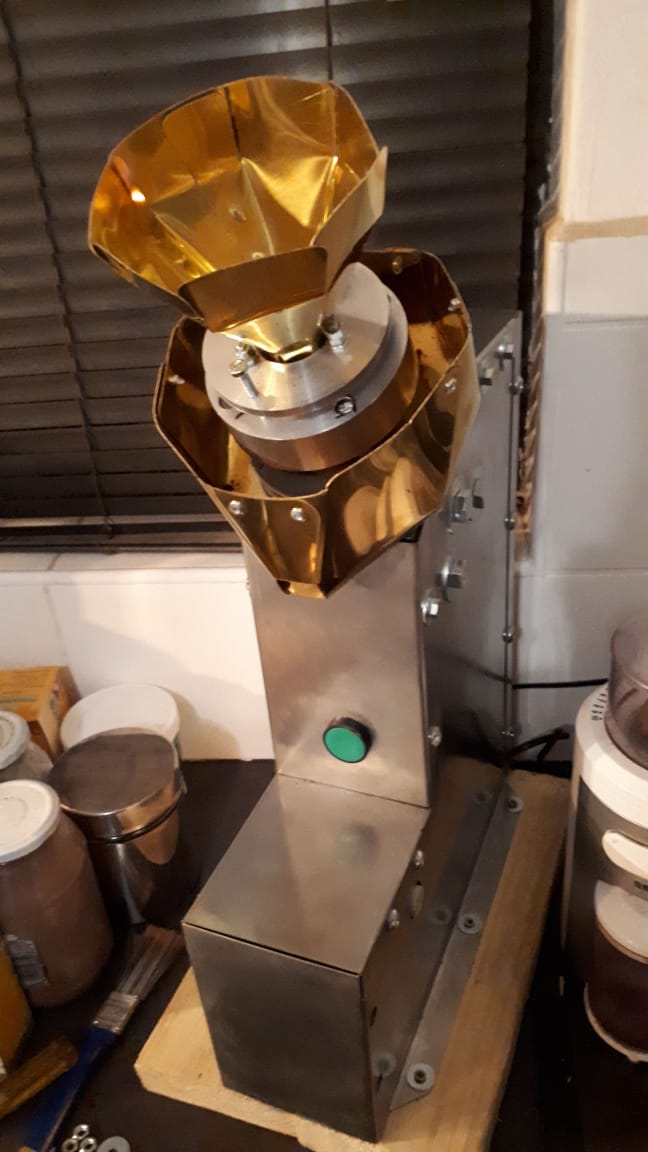
Above is a picture of the second prototype that was built. This was design 9 (Mk IX). It worked very well but it was difficult to assemble. The current model is design nr 10 (Mk X).
If you want to tinker on your own, here is the link to the GitHub repository for the designs of the Home Coffee Grinders.
https://github.com/benicovdw/Coffee-Equipment-Designs
Let's look at the designs and concept history that lead to these.
1st Design
I bought a set of 64mm Mazzer Jolly burrs and began to design a grinder around the burrs.

This was the first design. It quickly became obvious that it would be too expensive to build. Also, the motor was a problem. The STEP file for this design is open-sourced and can be obtained from the git repository above.
Design 2 (Mk II)

The idea with design #2 was to test the concept of having the top part rotating and the bottom part being a stationary gap adjuster. It is an "out-of-the-box" concept but not too practical. Also expensive to manufacture.
Design 3 (Mk III)

Design #3 attempted to bring the price down by using standard "off the shelf" bolts and nuts. The problem with this is that the "off the shelf" bolts and nuts of this size are expensive - and the machining people did not want to work with it. They preferred to make the components from scratch - and then the hexagons do not make sense. This idea had value since it formed the foundation for a workable configuration as used in Designs 8 and 9 (from which the first prototypes were built).
Design 4 (Mk IV)

Again the bottom (rotating part) is also the gap-adjuster. This is making the adjusting awkward and "on-the-fly" adjusting is non-existing. I constantly was trying to steer away from large diameter threads.
Design 5 (Mk V)

The problem with MK v was that the beans are being loaded through rotating holes ... not a good idea!
Design 6 (Mk VI)

Design 6 was basically the same as nr 5 - but with the bean loading inlet stationary (although too small).
Design 7 (Mk VII)

The idea behind Design 7, was that it could be built with a turning lathe in somebody's garage. It tries to use very simple disks and standard bolts and nuts.
Design 8 (Mk VIII)

Concept nr 8 introduced the controversial idea of using a drilling machine for the electric motor. I could not find a cheaper electric motor with speed control and a build-in gearbox.
Design 9 (Mk IX) rev2

The first prototype was built on this design. It worked well - but was cumbersome to adjust.

Design 9 (Mk IX) rev5
The second prototype was built using Design 9 revision 5. JP from VT Engineering convinced me to go for a large diameter threaded part for the gap adjusting. This made on-the-fly grind settings possible. The wooden case was also swapped for a stainless steel case.


Design 10 (Mk X)
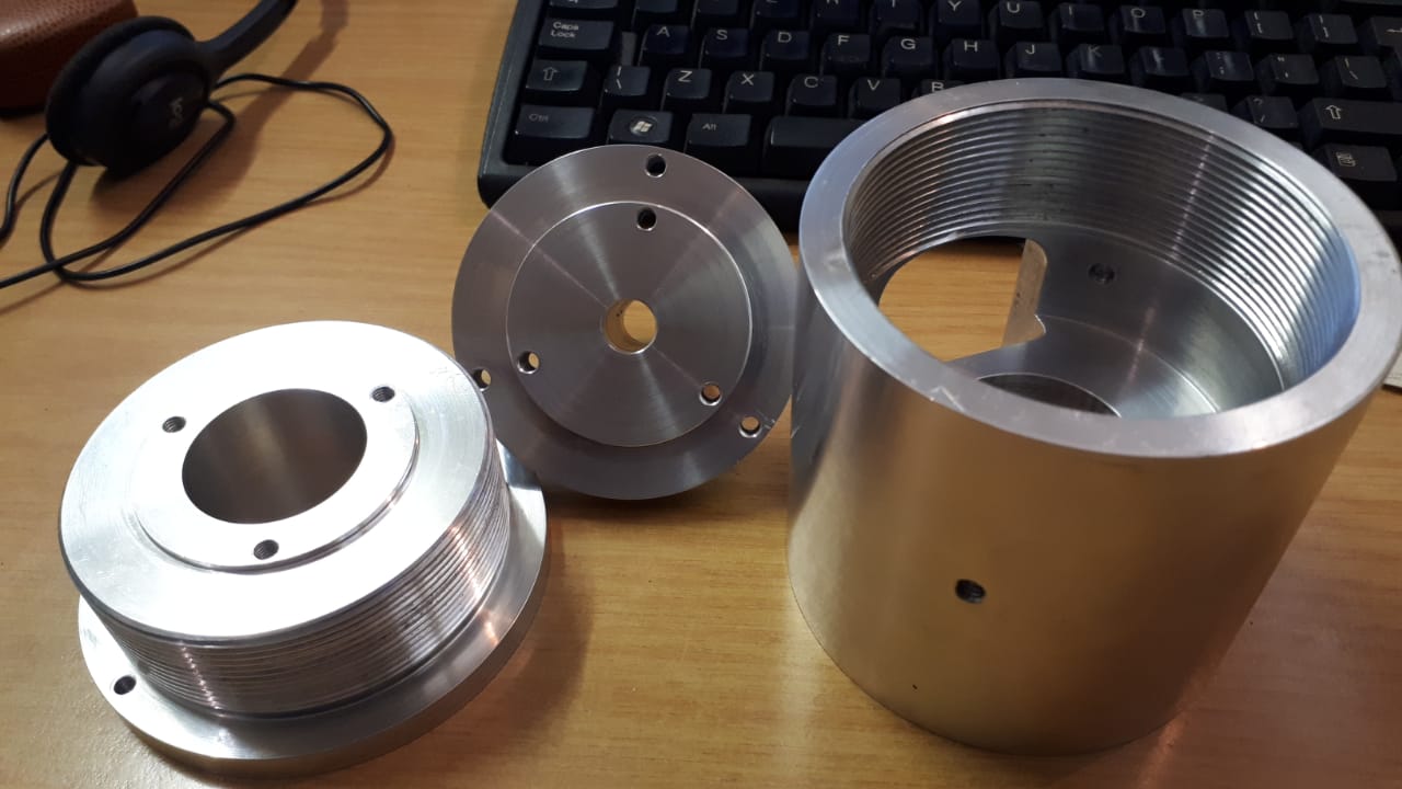
The current prototype (nr 3) is being built from Design #10. Design 10 has fewer parts because we make it on a CNC machine. The bodies of the grinders were all made from Aluminium.
The case can be made from 0.5mm steel or stainless steel or even brass plate. It is designed to be laser cut and can be bent by hand.

The manufacturing drawings for this design are available in the store. We did not like the boxy shape above - so this is how it looks currently:


You can get the STEP, dxf and pdf files to build your own version of the above designs from the Github page: https://github.com/benicovdw/Coffee-Equipment-Designs